Hardware overview
SOIC Version
Last Version
![]()
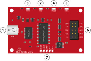
1. Mini-B USB port. Connects the Bus Pirate to a PC. The Bus Pirate draws power from the USB port, and uses the data connection to communicate with the PC.
2. USB transmit indicator. This LED flashes when there's traffic from the PIC to the PC.
3. Power indicator. This LED lights when the Bus Pirate is powered by the USB supply.
4. Mode indicator. This LED lights when the Bus Pirate is configured for a protocol mode from the user terminal (menu 'm'). The I/O pins might be active when the mode indicator is on. The pins should be in a safe, non-powered, high-impedance state when the mode LED is off.
5. Voltage regulator indicator. This LED lights when the on-board power supplies have been activated from the user terminal (command capital 'W' ).
6. I/O pins. This 2x5 block of 0.1" pin header connects the Bus Pirate to external circuits. See the pinout table below, or the Bus Pirate manual.
![]()
Image shows Colors from BusPirate ProbeKit available at Seeed Studio on latest Version
Notes: * TX moved from CS to MOSI in firmware v0g
7. In circuit serial programming (ICSP) header. This 1x5 block of 0.1" pin header is the programming connection for the PIC 24FJ64GA002 microcontroller. These pins can be used to write new firmware to the microcontroller with a programmer like the PICKIT2 or ICD2 . The Bus Pirate firmware can also be updated over the USB connection using a bootloader, so the ICSP header is normally only used to program it the first time at the factory. Put a jumper between the PGC and PGD pins to trigger the on-board bootloader for firmware updates.
8. Serial terminal (ST) header. Version v2go only. This unpopulated header is a tap into the UART connection between the PIC microcontroller and the FTDI 232BL chip that provides the USB connection. The Bus Pirate firmware defaults to a 115200bps/8/N/1 UART.
Last Version
1. Mini-B USB port. Connects the Bus Pirate to a PC. The Bus Pirate draws power from the USB port, and uses the data connection to communicate with the PC.
2. USB transmit indicator. This LED flashes when there's traffic from the PIC to the PC.
3. Power indicator. This LED lights when the Bus Pirate is powered by the USB supply.
4. Mode indicator. This LED lights when the Bus Pirate is configured for a protocol mode from the user terminal (menu 'm'). The I/O pins might be active when the mode indicator is on. The pins should be in a safe, non-powered, high-impedance state when the mode LED is off.
5. Voltage regulator indicator. This LED lights when the on-board power supplies have been activated from the user terminal (command capital 'W' ).
6. I/O pins. This 2x5 block of 0.1" pin header connects the Bus Pirate to external circuits. See the pinout table below, or the Bus Pirate manual.

Image shows Colors from BusPirate ProbeKit available at Seeed Studio on latest Version
| Pin Name | Description (Bus Pirate is the master) |
|---|---|
| MOSI | Master data out, slave in (SPI, JTAG), Serial data (1-Wire, I2C, KB), TX* (UART) |
| CLK | Clock signal (I2C, SPI, JTAG, KB) |
| MISO | Master data in, slave out (SPI, JTAG) RX (UART) |
| CS* | Chip select (SPI), TMS (JTAG) |
| AUX | Auxiliary IO, frequency probe, pulse-width modulator |
| ADC | Voltage measurement probe (max 6volts) |
| Vpu | Voltage input for on-board pull-up resistors (0-5volts). |
| +3.3v | +3.3volt switchable power supply |
| +5.0v | +5volt switchable power supply |
| GND | Ground, connect to ground of test circuit |
7. In circuit serial programming (ICSP) header. This 1x5 block of 0.1" pin header is the programming connection for the PIC 24FJ64GA002 microcontroller. These pins can be used to write new firmware to the microcontroller with a programmer like the PICKIT2 or ICD2 . The Bus Pirate firmware can also be updated over the USB connection using a bootloader, so the ICSP header is normally only used to program it the first time at the factory. Put a jumper between the PGC and PGD pins to trigger the on-board bootloader for firmware updates.
8. Serial terminal (ST) header. Version v2go only. This unpopulated header is a tap into the UART connection between the PIC microcontroller and the FTDI 232BL chip that provides the USB connection. The Bus Pirate firmware defaults to a 115200bps/8/N/1 UART.
Retrieved from "http://dangerousprototypes.com/docs/Hardware_overview"
FTDI driver install and configuration

Windows will request a driver the first time the Bus Pirate connects to a PC. Extract the 2.08.28 virtual com port drivers from FTDI into a folder and browse to them using the 'Found New Hardware' wizard. Note: the 2.08.30 drivers gave some people connection errors between the Windows terminal and the Bus Pirate. For now we advise to install the 2.08.28 drivers. Install guides and drivers for other systems are also available on the FTDI driver download page.

To find the COM port number assigned to the Bus Pirate go to the Windows device manager (Start->Settings->Control panel->System->Hardware->Device manager). Look in 'Ports (COM & LPT)' for 'USB Serial Port', ours is COM5.

You can change the serial port assigned to the FTDI chip. Go to USB Serial Port properties->Port settings tab->Advanced, change the COM port in the drop-down box.
Terminal setup
Windows terminal is cranky, but it appears to work with the Bus Pirate when VT100 emulation is enabled. We highly recommend a better terminal, we like Tera Term Profor Windows.

First, configure the correct COM port and settings. The Bus Pirate operates at 115200bps/8/N/1 on the COM port assigned by Windows. Flow control is no longer required. Disable it!

Next, check the terminal setup. Turn off local echo and use a VT100 terminal type. The Bus Pirate should work with any type of new-line character, but we use the CR setting.
Get to know the terminal interface
The Bus Pirate is controlled by text commands entered through the serial terminal. If the terminal is blank, press enter to show the command prompt. Press '?', followed byenter, to show the help menu.
- Menus configure various Bus Pirate options like pull-up resistors, terminal speed, data display format (DEC, HEX, BIN), etc. Type the menu command, followed byenter, to display the options.
- Syntax is used to interact with a device connected over a bus. Commands are mostly single characters, such as 'r' to read a byte. Enter up to 4000 characters of syntax, press enter to execute the sequence.
Each menu and syntax option is documented fully in the Bus Pirate manual.
Most menus have a default option shown in () before the prompt:
Output type:
1. High-Z outputs (H=input, L=GND)
2. Normal outputs (H=Vcc, L=GND)
(1) > <<< option 1 is the default
1. High-Z outputs (H=input, L=GND)
2. Normal outputs (H=Vcc, L=GND)
(1) > <<< option 1 is the default
Press enter to select the default option.
Bus modes, protocol libraries
General Protocol interaction
---------------------------------------------------------------------------
? This help (0) List current macros
=X/|X Converts X/reverse X (x) Macro x
~ Selftest [ Start
# Reset ] Stop
$ Jump to bootloader { Start with read
&/% Delay 1 us/ms } Stop
a/A/@ AUXPIN (low/HI/READ) "abc" Send string
b Set baudrate 123
c/C AUX assignment (aux/CS) 0x123
d/D Measure ADC (once/CONT.) 0b110 Send value
f Measure frequency r Read
g/S Generate PWM/Servo / CLK hi
h Commandhistory \ CLK lo
i Versioninfo/statusinfo ^ CLK tick
l/L Bitorder (msb/LSB) - DAT hi
m Change mode _ DAT lo
o Set output type . DAT read
p/P Pullup resistors (off/ON) ! Bit read
s Script engine : Repeat e.g. r:10
v Show volts/states . Bits to read/write e.g. 0x55.2
w/W PSU (off/ON)
HiZ>m 0>
1. HiZ
2. 1-WIRE
3. UART
4. I2C
5. SPI
6. 2WIRE
7. 3WIRE
8. LCD
9. DIO
x. exit(without change)
The 'bus mode' menu (M) configures the Bus Pirate for a specific protocol, like 1-Wire, I2C, SPI, etc. The default start-up mode is HiZ, all pins are inputs and all power supplies are off.
(1)>5 <<< enter SPI bus modeSet speed:
1. 30KHz
2. 125KHz
3. 250KHz
4. 1MHz
(1)>1
Clock polarity:
1. Idle low *default
2. Idle high
(1)>1
Output clock edge:
1. Idle to active
2. Active to idle *default
(2)>2
Input sample phase:
1. Middle *default
2. End
(1)>1
CS:
1. CS
2. /CS *default
(2)>2
Select output type:
1. Open drain (H=Hi-Z, L=GND)
2. Normal (H=3.3V, L=GND)
(1)>2 <<< option 1 is the default
Ready
SPI>W
Power supplies ON
SPI>w
Power supplies OFF
SPI>V
Syntax error at char 1
SPI>v
Pinstates:
1.(BR) 2.(RD) 3.(OR) 4.(YW) 5.(GN) 6.(BL) 7.(PU) 8.(GR) 9.(WT) 0.(Blk)
GND 3.3V 5.0V ADC VPU AUX CLK MOSI CS MISO
P P P I I I O O O I
GND 0.00V 2.43V 0.00V 0.00V L L L H L
SPI>W
Power supplies ON
SPI>
Power supplies
3.3volt and 5volt on-board power supplies can provide up to 150mA for your project. Activate them with the w/W command from any mode except HiZ mode. HiZ mode is a safe mode and all outputs are disabled.
I2C>w<<
POWER SUPPLIES OFF
I2C>v<<
Voltage monitors: 5V: 0.0 | 3.3V: 0.0 | VPULLUP: 0.0 |
I2C>W<<
POWER SUPPLIES ON
I2C>v<<
Voltage monitors: 5V: 4.9 | 3.3V: 3.2 | VPULLUP: 0.0 |
I2C>
POWER SUPPLIES OFF
I2C>v<<
Voltage monitors: 5V: 0.0 | 3.3V: 0.0 | VPULLUP: 0.0 |
I2C>W<<
POWER SUPPLIES ON
I2C>v<<
Voltage monitors: 5V: 4.9 | 3.3V: 3.2 | VPULLUP: 0.0 |
I2C>
Capital 'W' activates the on-board supplies, small 'w' turns them off. Turn the power supplies on, then press v to show a power supply voltage report.
Note that W is syntax and not a menu option, it can be used with other syntax to toggle the power in the middle of complex bus operations.
The power supplies will try to protect your project with over current protection. Additionally, the Bus Pirate will measure the voltage shortly after the supplies are enabled. If a short is detected it will disable them and show a warning. This may help minimize damage to a project when there is a short or problem on a new board.
Demo with AT25080A/160A/320A/640A on Aardvark I2cC/SPI Activity Board
Instruction Set for the AT25080A/160A/320A/640A
Instruction Name Instruction Format Operation
WREN 0000 0110 Set Write Enable Latch
WRDI 0000 0100 Reset Write Enable Latch
RDSR 0000 0101 Read Status Register
WRSR 0000 0001 Write Status Register
READ 0000 0011 Read Data from Memory Array
WRITE 0000 0010 Write Data to Memory Array
A quick way to find the command to access a register:
- Use the Bus Pirate to find the binary equivalent (= command)
Lower chip select ([), then setup the register to access(0x05), read a byte (r), and raise chip select (]).
/CS ENABLED
WRITE: 0x00
WRITE: 0x4D
READ: 0x00
/CS DISABLED
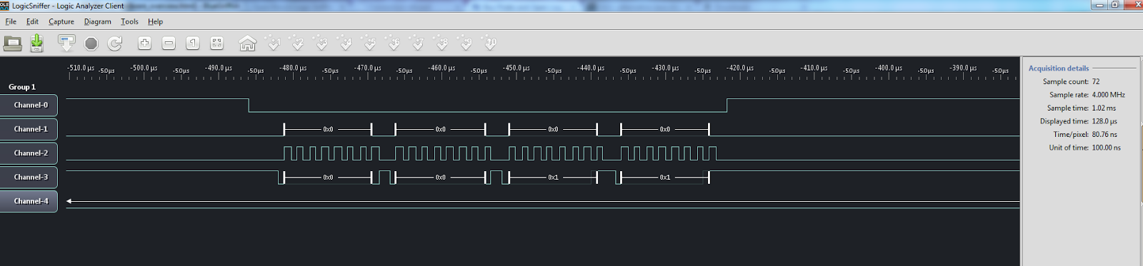
Open Logic Analyzer Client
http://www.lxtreme.nl/ols/
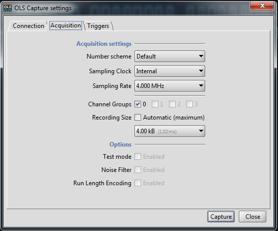

The Bus Pirate V3 can store 4kB of data and can sample at a maximum rate of 1MHz. In this example we analyzed
communication at 125kHz on the aardvark so we need to set the speed at a fast enough rate to be able to capture
the transitions from high to low and low to high. It is recommended that you choose a sampling rate 10x your
communication rate but in reality it can be lower.
Click on the Trigger Enabled tick box to turn the triggers on.
At the bottom of this screen you will see Mask / Value tick boxes going from 0 to 31. Our Bus Pirate only has 5 logic inputs so 5 through to 31 are greyed out. Tick in the Mask boxes any inputs that you want a trigger enabled on. Value bits are currently ignored, any change triggers the capture.
For SPI select 0,1,2,3 where